|
|
NEXCOM Networking and Communication: Powerful Enterprise Networking Solution for Cybersecurity Application
NEXCOM Network and Communication Solutions Busines...
NEXCOM Networking and Communication: Powerful Enterprise Networking Solution for Cybersecurity Application
|
|
|
NEXCOM, Stand Up to the Challenges of OT Network Security
Learn how NEXCOM’s ISA 140 addresses everyday chal...
NEXCOM, Stand Up to the Challenges of OT Network Security
|
Surge Immunity by Design: EMC Strategies for IEC 61850/IEEE 1613 Network Gateways
The Trend
Modern substation automation systems designed for IEC 61850 and IEEE 1613 environments are often deployed near high-energy switching equipment, long cable runs, thus are subjected to ESD and non-ESD surges (lightning and switching transients) as well as grid-level disturbances—conditions that introduce high-energy, microsecond-scale surge events far beyond what traditional IT-grade equipment typically encounters.
As digital substations evolve toward higher bandwidth, deeper integration, and lower power margins, their interfaces—Ethernet PHYs, serial ports, I/O sensors, and control modules—become more susceptible. The industry is thus moving from component-level immunity toward system-level surge-path engineering.
This shift resembles a growing city preparing for heavier seasonal storms: expanding infrastructure requires smarter and more coordinated flood-control strategies.
The Challenge
Many engineering teams encounter a recurring trap: misreading the initial signs of EMC failure. Incorrect interpretation leads them to modify secondary parameters—filter values, connector choices, or board spacing—without addressing the true root cause.
As in a city overwhelmed by sudden floods, focusing only on local drainage (e.g., adding more capacitors) without understanding the hydrology (the surge coupling path) causes repeated failures and non-convergent experiments.
At the core, every surge problem consists of three inseparable elements:
- Interference Source: the defined output of the surge generator (lightning or switching equivalent).
- Coupling Path: cable, air-gap, enclosure, and PCB routes through which energy travels.
- Sensitive Victim: interface ICs, insulation barriers, or low-voltage control signals.
Failure arises when engineers skip systematic coupling-path analysis—the “city map” of where the electrical flood will travel.
Surge waveforms specified in IEC/IEEE tests (1.2/50 μs, 8/20 μs, 10/700 μs) carry relatively low high-frequency content but extremely high energy. That makes their PCB discharge paths plan-able, much like flood channels and levees built in anticipation of heavy rain.
The challenge is not the unpredictability of surges—it is the misunderstanding of how and where the surge will travel inside a system.
A Better Solution
NEXCOM employs a structured, multi-layer surge-protection methodology—conceptually similar to a citywide flood-mitigation system. NEXCOM designs discharge paths from connector entry points to the grounding bolt as a continuous route—not a scattered set of add-on protections. This planning is similar to city engineers aligning rivers, diversion channels, pump stations, and gates into one unified flood management network [Figure 1].

Figure 1. Integrated flood management system.
The foundation of this approach is a key surge protection principle: energy should be released to the ground as quickly as possible, and every effort must be made to prevent it from entering the system. Accordingly, the selection, placement, and layout of components are critical. Proper component topology ensures that transient energy is intercepted and guided along planned discharge paths, protecting sensitive electronics from flooding.
The methodology begins by identifying the surge discharge destination (earth ground) and designing a controlled, low-impedance route for energy to exit the system. When the discharge direction is correct and these principles are applied systematically, most EMC challenges converge rapidly and remaining refinements become manageable. From this foundation, each of below elements is necessary component of the same integrated surge-immunity strategy.
Grounding Strategy — Main Canal
An effective surge-immunity design begins with the grounding strategy; it is the primary mechanism that determines whether surge energy has a safe and predictable escape route. PCB chassis-ground regions, enclosure bonding, and earth-reference points must be engineered to create a low-impedance path that conducts transient energy away from external interfaces and toward chassis ground, and ultimately to earth. Without this “main canal” even the most capable surge-protection components behave like isolated dams that eventually overflow due to no downstream river to drain into.
Determining where surge energy will be discharged is therefore one of the foundational steps in system-level and PCB-level topology design. A poorly planned or indirect discharge path severely limits the effectiveness of any protection component, particularly when facing different surge test levels.
A robust grounding strategy with a clear, unobstructed discharge route is analogous to a city’s main flood-diversion channel: the entire protection architecture depends on it, and every other defensive layer is designed around this fundamental flow path.
Mitigation — Sluice Gates (GDT, TSS, TVS)
Mitigation components activate only when surge levels exceed their threshold, creating a low-impedance channel to ground. Gas discharge tubes (GDT), thyristor surge suppressors (TSS), and transient voltage suppressors (TVS) operate like floodgates: they open under high water and divert excess energy to safe regions. Their placement and conduction path determine how effectively the surge is removed before it reaches vulnerable circuits.
Blocking — Levees and Barriers (Isolation & Impedance)
Isolation transformers and high-impedance elements block common-mode energy from entering the system, similar to levees preventing floodwater from overtopping residential districts. Their insulation level and creepage/clearance distances correspond directly to the required surge rating—analogous to designing a levee for a 100-year or 200-year flood standard.
Decoupling — Flow Regulators
Decoupling inductors distribute surge energy so upstream surge protective devices (SPDs) absorb the majority, protecting smaller, downstream components. They serve as hydraulic locks, slowing water flow to prevent structural overload.
Residual Voltage Smoothing — Multi-Functional Flood Detention Basin
Modern flood detention basins are designed not only for peak-flow control but also for water-resource utilization. In normal conditions, they collect and store rainwater, enabling purification and reuse for municipal, industrial, or agricultural demand. When heavy storms arrive, the same system shifts into a regulatory mode—absorbing excess inflow, attenuating peak water levels, and preventing downstream flooding. This dual-purpose infrastructure delivers both everyday stability and emergency protection within one coordinated design.
In surge-immunity engineering, residual-voltage smoothing serves a similar role. After upstream surge-mitigation stages divert and dissipate the high-energy portion of a transient, LC filters and parallel capacitors stabilize the remaining voltage. These components act as electrical “detention basins,” absorbing residual fluctuations, regulating low-frequency deviations, and ensuring that the output delivered to downstream ICs remains within tolerance. The power stage continues to function normally, providing stable, compliant power even immediately after a surge event—much like a well-designed detention basin ensures a city’s water system remains reliable across both calm and storm conditions.
Special emphasis is placed on Ethernet port surge protection, as it directly supports IEC 61850 system architecture. IEC 61850 is fundamentally an Ethernet-based protocol, deployed over both copper and fiber interfaces, making Ethernet ports the primary ingress point for surge energy in modern substations. As a result, Ethernet protection is prioritized to address the dominant operational and exposure pathways in contemporary substation networks.
Differential-mode surge, or the transfer of transient energy from common mode [Figure 2] to differential mode [Figure 3] caused by an isolation transformer’s parasitic parameters, can cross from the primary to the secondary side—much like a flood overtopping a levee.
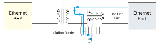
Figure 2. Common mode current flow.
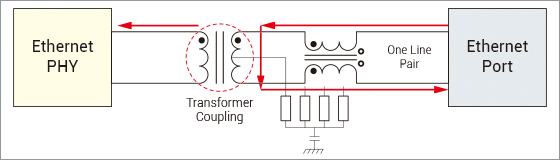
Figure 3. Differential mode current flow.
TVS components must be added to protect the PHY IC, just as a local drainage system must function to safeguard homes even after a levee overflows [Figure 4].
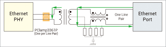
Figure 4. Differential mode current flow with TVS diode.
In IEC 61850/IEEE 1613 deployments, where uptime is a regulatory expectation, NEXCOM’s engineering approach elevates EMC from a pass/fail test hurdle to a long-term operational asset. By combining disciplined discharge-path planning with carefully selected components, NEXCOM designs systems that maintain “set-and-forget” reliability, support extended asset life cycles, and avoid becoming maintenance burdens themselves. This reduces unnecessary site interventions and minimizes premature hardware replacement, reinforcing predictable performance over years of field operation.
Conclusion
Through a structured understanding of surge sources, coupling paths, and sensitive victims, surge immunity becomes an engineering discipline. The urban flood-control analogy demonstrates that effective EMC design is not about adding more protection, but about planning the right protection in the right locations.
For IEC 61850/IEEE 1613 equipment in substation environments, NEXCOM applies this methodology to ensure surge energy is guided, diverted, and dissipated predictably. This approach meets stringent immunity requirements while maintaining system continuity, demonstrating NEXCOM’s proficiency in translating surge-protection principles into reliable, real-world designs.